Project Tsunami
or
3 years of work due to a bet about a crate of
Bitburger beer
Burkhard, DF5XV, www.classicbroadcast.de, owns a Monster-PA of R&S called VK20. The live weight of this PA amounts to 1.6 metric tons, it needs a big room on its own with a defined supply and exhaust air and its output reaches frightening 20 Kilowatts, even for RTTY. As a driving transmitter a R&S SK01 is required. Burkhard has an official permission of the BNA for 20 KW on shortwave for broadcast, although not for ham radio. Such enormous values of transmitting power challenge even the creativity of an experienced high frequency engineer. Well, three years ago, the of this article placed a bet against Burkhard to build a power amplified with more than half the output power of the VK20 in SSB mode, yet would fit the trunk of a compact car as well as a manageable weight. Burkhard's answer: No way! So the race was on!
After three years have passed, the project with working title “Tsunami” is finally completed. Even the additional difficulty of a minimal required input power of only 100 Watts, achieved by every amateur transceiver, in order to attain the full SSB transmit power of approximately 15 Kilowatts was accomplished. A total amplification of about 21 dB is technically very ambitious as it was not the goal to build a power oscillator.
The tube which satisfies the technical requirements of the project “Tsunami” for sure without reaching its limits is the 4CX10000D. According to the Eimac spec sheet for SSB linear
Click to enlarge image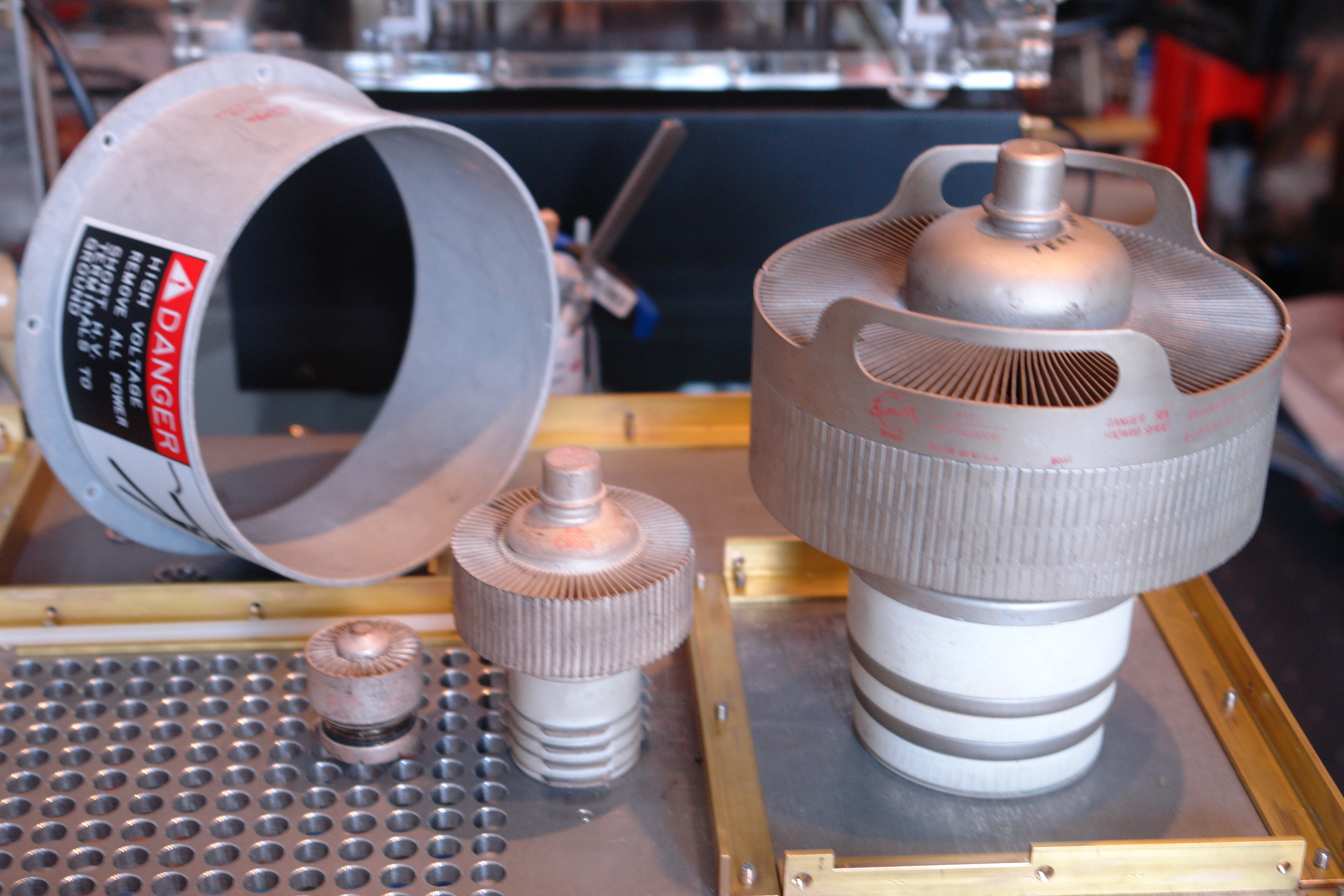
Fig.1: Size comparison: 4X150A, Pv = 250 W / 4CX1500B, Pv = 1500 W / 4CX10000D, Pv = 12000 W
The 322 holes in the 8 mm floor
panel (underneath the transformer) are used as a cooling air intake.
amplification applications, this tetrode features a plate dissipation of 12 Kilowatts (Ua, max: 7500 V, Ia, max: 4 A) and provides a continuous output of 16 Kilowatts within the guaranteed values by Eimac. The plate input power results in 25 Kilowatts in this case. If the heating power of 563 Watts, the power of the screen and control grid as well as for the fan and other system requirements is added, a powerful three-phase alternating current adapter is necessary. The fuse box of the single family house owned by the author provides a connection with 3 times 40 Amps at 400 Volts, hence a continuous power rating of 28 KVA. This is barely enough for a 16 Kilowatts continuous carrier – doing ones laundry in a washing machine at the same time should be avoided, though.
Of course, in SSB mode this calculation is different. Without a voice compressor the average power in an OM-typical continuous QSO is only 20 to 25 percent of the peak power, with the use of a compressor the average power increases up to 30 percent. The plate high-voltage transformer of the Tsunami power amplifier is designed for 10 KVA, because for a SSB output power of 15 Kilowatts with an amplifier efficiency of 65 percent and an average voice power of excessive 33 percent (with dreadful contest modulation), the required transformer power amounts to 7.6 KVA (15 KW / 0.65 x 0.33). Thus, a 10 KVA transformer is more than sufficient to conduct comprehensive continuous QSOs in SSB. In case one listens to the dialog counterpart once in a while, the dimensions of the plate transformer is downright luxurious.
Click to enlarge image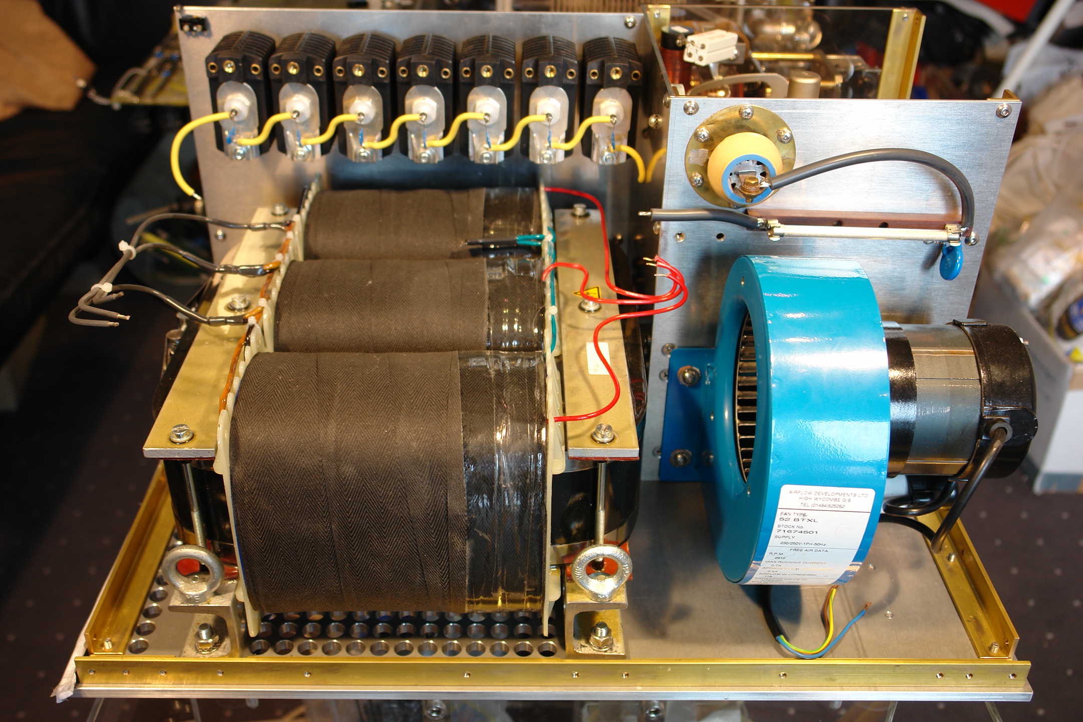
Fig. 2: 10 KVA three-phase alternating current tape wound hypersil plate transformer, weighs only 70 Kilograms. Underneath the transformer one can see the 322 holes of 12 mm diameter, allowing for an especially quiet cooling air intake also cooling the transformer
Additionally, the Tsunami power amplifier uses a 1.2 KVA toroidal core transformer for the remaining voltages. To power on the whole amplifier, a 1 VA transformer on the central motherboard is allotted. The turn-on procedure is designed to be very soft and after exactly 10 seconds the amplifier is ready for full power.
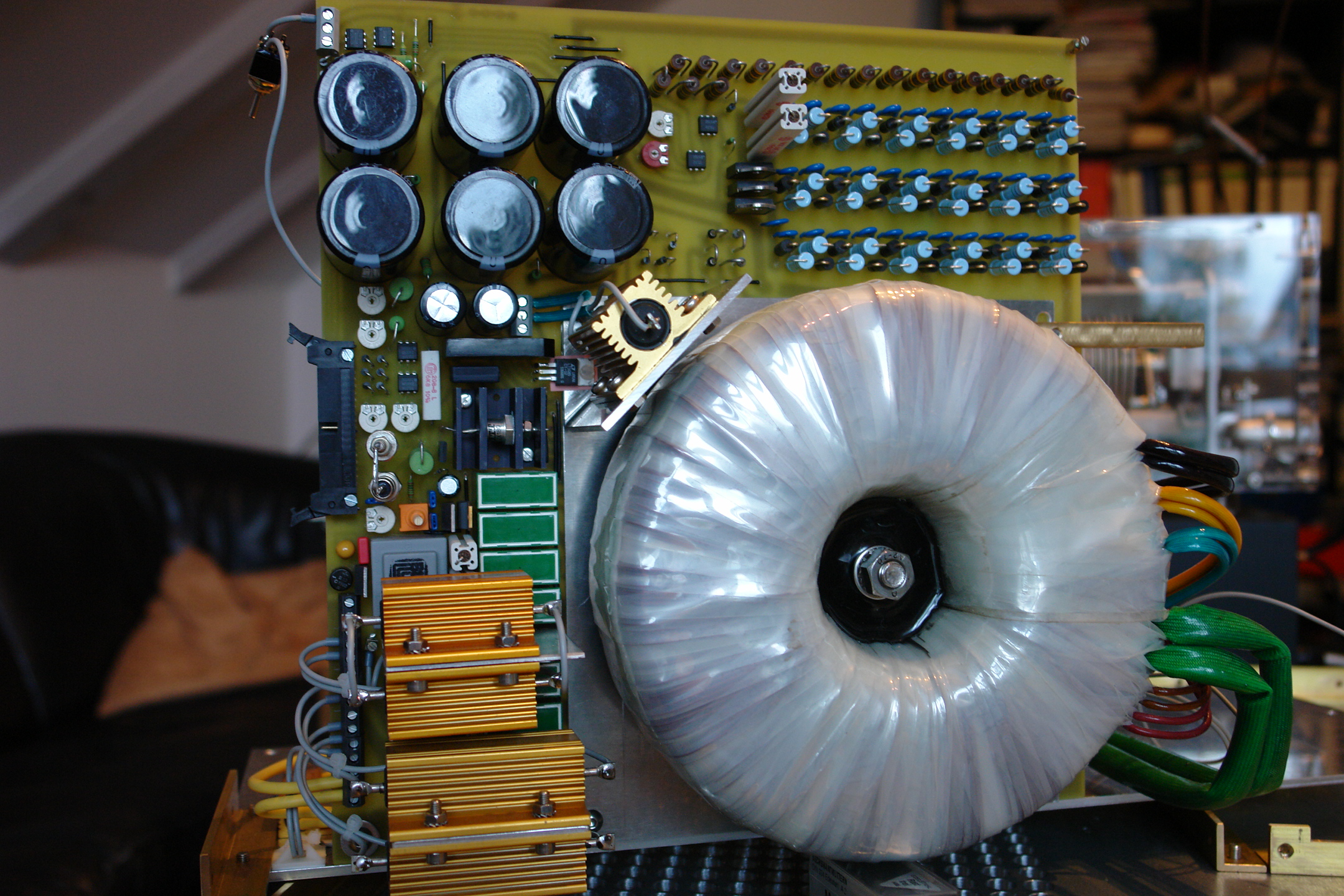
Fig. 3: Main board with 1200 VA toroidal core transformer (green connectors: 7.5 V - 75 A heating current), 1 VA transformer (center right, partly beneath golden resistor) for powering-on, 7800 V three-phase alternating current rectifier (top right), gold colored powering-on resistors (3 x 68 Ohms, 100 Watts, lower left), parts of the electronic controller of the control grid
After the dimensions of the main electronic components were determined, it was the constructor's ambition to build the world's only desktop output stage using a 4CX10000D which would fit on any reasonable station table. It is impossible to construct a smaller 15 KW SSB power amplifier: the total height of the “Tsunami” is only 31 cm. There is a voltage of 1000 V but only 8 mm of space between the bottom of the housing and the tube socket. Between the plate and the housing cover there is a voltage of 7000 V but only a gap of 22 mm. Although these distances are sufficient even at high humidity (e.g. after DX activity), smaller clearances are unfeasible. Also, the width of the amplifier is reduced due to the plate transformer and the roller inductor to an optimum of 57.5 cm. The same applies for its depth: 58.5 cm. A smaller 15 KW SSB power amplifier is definitely impossible!
The air flow for cooling was optimized. Cold air is sucked in bellow the anode transformer, keeping it cool at the same time. The warm air is then taken out on the shortest path above the plate. Of course, the best and most quiet fan available is used and mounted to the housing with a rubber joint to minimize vibrations. Also, on reception, the fan speed is reduced to further minimize noise. Still, the radial fan is dimensioned to absolutely be on the safe side, so the air flow through the amplifier tube is increased when transmitting, which is not quite inaudible. But the amplifier stays cool even during non-stop operation.

Fig. 4: On the bottom: three-phase alternating current hypersil plate transformer with 10 KVA, on top the central controller board with a toroidal transformer with 1200 VA (green connectors: 7.5 V / 75 A heating current), fan (blue), 7 Zener diodes (50 W each) for the screen grid (behind the toroidal transformer). Two Zener diodes (50 W each) as bias voltage of the precise electronic voltage control for the control grid are mounted to the rear panel. Plate fuse and feed through capacitor (top right), front panel with display board and digital control system for all switching operations (10 ms timing) of the amplifier as well as the control logic for the motors of two variable vacuum capacitors (left).
The configuration of the power amplifier without the front panel is depicted in Fig. 5. A ribbon cable connects the central main board with the display and control board on the back of the front panel. This display and control board also contains the complete processing logic of the amplifier as well as the Darlington transistors to directly control of all power relay. The power or RF relays will definitely not be triggered under load. Therefore, even the vacuum relays are working under optimal conditions. Fig. 6 shows the configuration of the front panel without push-buttons and switches. By the way: the advantage of LED displays is their ability to display PEP values without indolence.
In order to provide a stable operation of an power amplifier featuring an amplification of 21 dB, a transformation of the input voltage to the required driving voltage of the tube (approx. 245 V), an excellent RF insulation between tube input and output as well as additional neutralization of the tube is required. The insulation between tube input and output was achieved by galvanically grounding the screen grid and the installation of an additional mechanical perforated grid between screen grid and the plate of the tube at the same time. This mechanical effort depicted in Fig. 7 has never been reported before in public descriptions, so this might be a new idea. The screen grid was also grounded using 8 low capacitance connections. Fig. 7 also presents the RF plate choke of 112 uHy and the 8 KV feed through capacitor. The plate choke was supplied with an adjustable short circuit ring (silver wire with Teflon hull) in order to put two resonance points in the center between amateur bands.

Fig. 5: Front view without front panel, side plates and back board. Three-phase alternating current high voltage plate transformer (bottom right), central power supply board with toroidal transformer (above plate transformer), 7 x Zener diodes for the screen grid (center top), roller inductor (top left), cogwheel (bottom center) for switching the control grid transformer parts (compensating the input capacitance of the tube and neutralizing the tube itself, 11 switching positions for all amateur short wave bands)
Click to enlarge image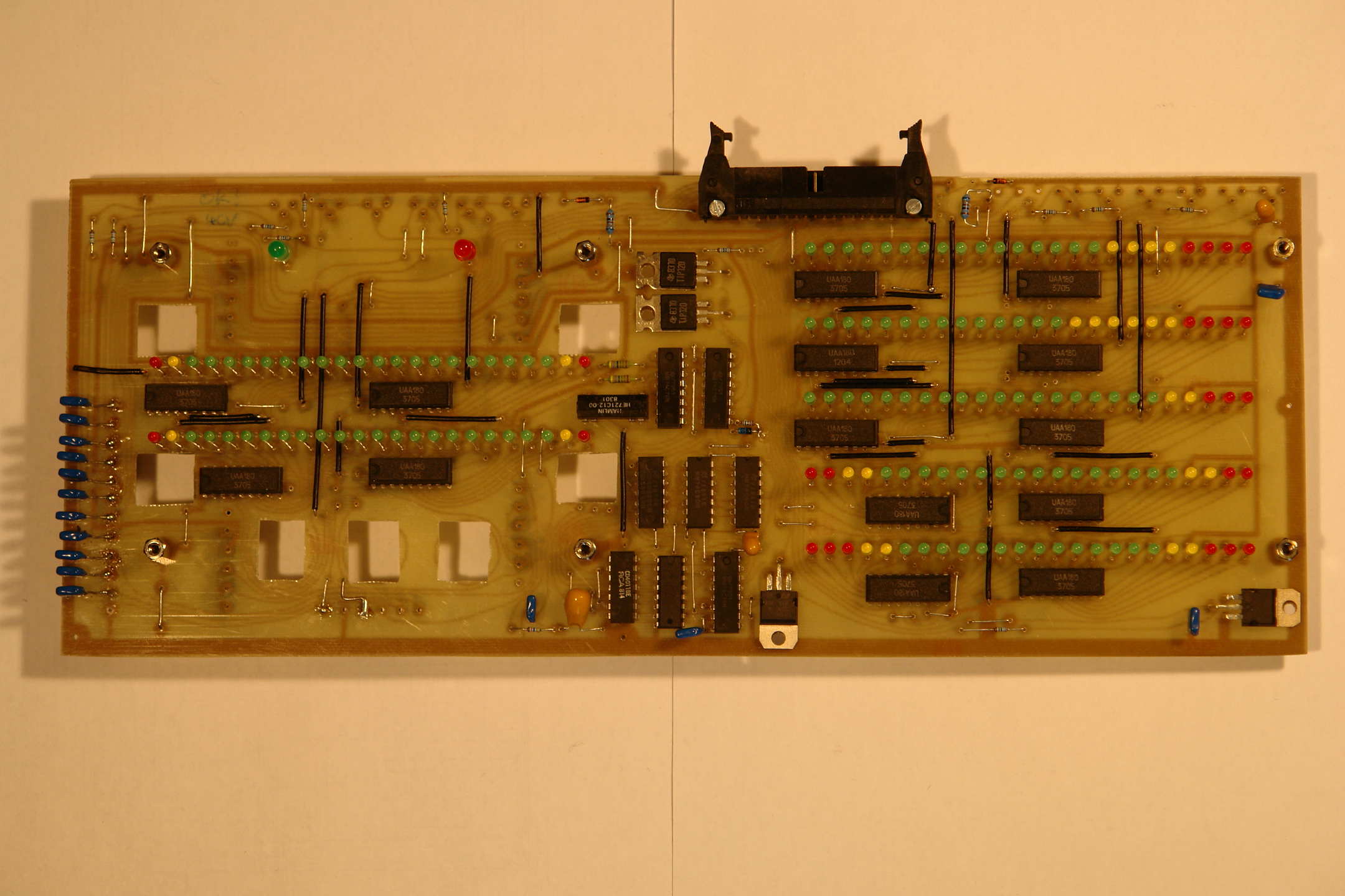
Fig. 6: Display and control board: the 8 ICs in the center control all PA functions with a 10 ms timing
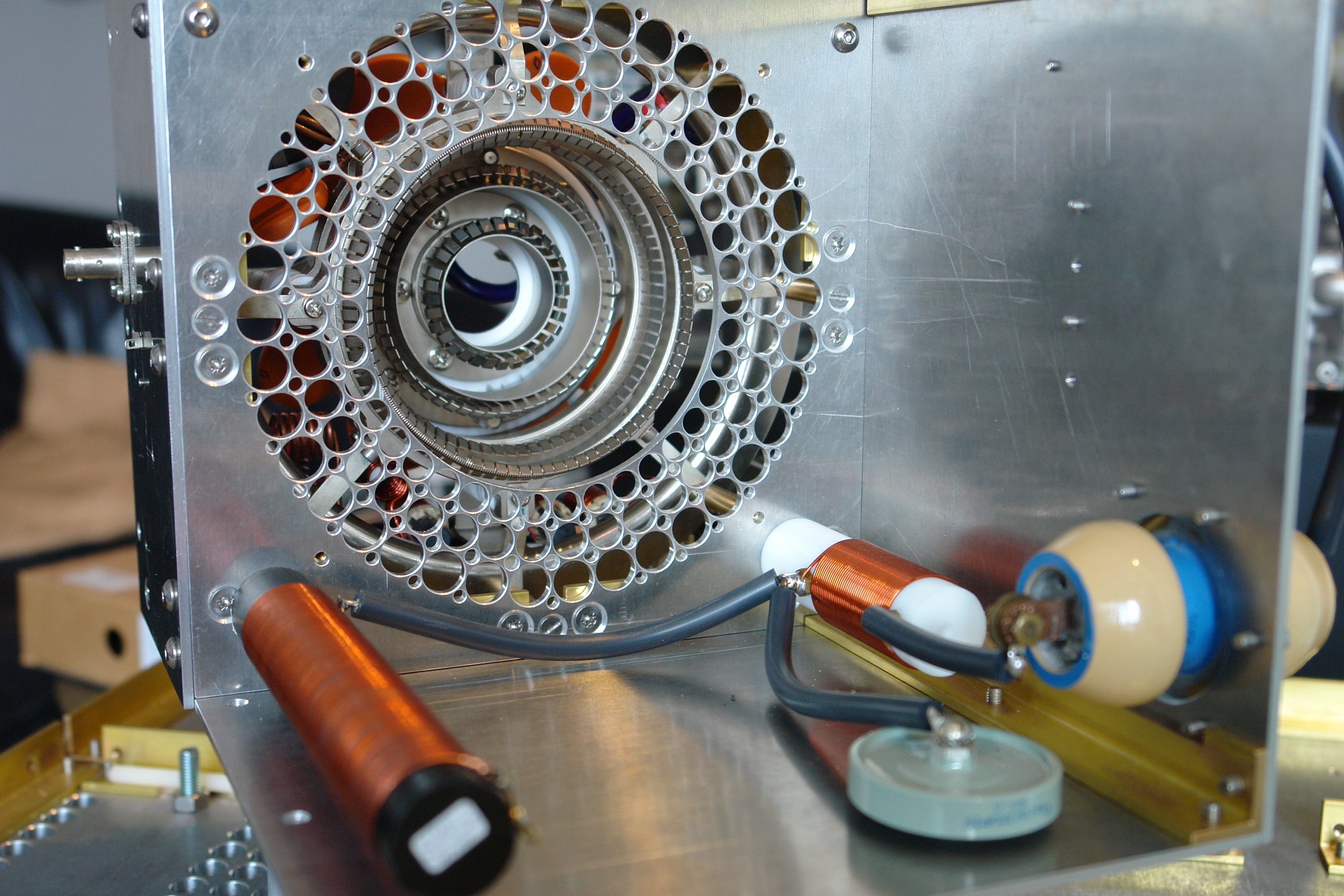
Fig. 7: RF insulation of the grid area from the plate area by a perforated metal plate of 4 mm thickness. The eight low inductive ground connection of the screen grid are visible directly behind the perforated plate. Instead of the smaller second RF plate choke a 2 pF capacitor was later installed for neutralization
The modular tube package is depicted from the grid side in Fig. 8. The heating current (7,5 V / 75 A) is provided by the blue wires (2 x 16 mm²) whereas the orange ceramic capacitors (4,7 nF / 6,3 KV) are the bypass capacitors which will RF technically ground the cathode on the shortest path. On the top right the input transformer is visible. This transformer with ratio 1:4 was replaced by another transformer with ratio 1:9 (tripling the voltage). The generously dimensioned RF input resistor has 450 Ohms at a 500 Watts input. The band switching is done by an 11-pole rotary switch. In the final version this switch was equipped with two layers, one for optimizing the input SWRs, and the other for neutralization. Also the coils for compensation of the different bands are partly visible. The modular and compact construction of the tube unit is very solid and easily accessible for service and optimization. The neutralization of the unit is carried out with heating and control grid voltage applied. Each and every band was optimized with respect to the input SWRs and neutralization with great precision, which was very tedious but the essential key for the success of the project. There is a distinct switch position for each band; the broad 10 m band however requires three positions. But of course the Tsunami power amplifier works stable even without neutralization, but the amplification is lower in this case and is slightly dependent on the frequency. So for perfect operation at an amplification of 21 dB all technical possibilities must be exploited. But the results of superior RF production with unrestrained power compensate for the costly calibration work. With an input power of only 5 Watts an output of 750 Watts is achieved. With 30 Watts input the output power reaches 4400 Watts. Even with an SSB input power of 100 Watts the gain remains constant, i.e. the output power amounts to (40 m) 14.6 KW. The tube is not really challenged and demonstrates well-being and nonchalant performance. Only the terms of license are not really humored if the antenna shall be used as a load resistor. Unfortunately, a 5 KW
dummy load by Bird was not really humored as well and quit its service with a loud bang after about 6 seconds of a 10 KW load (taking the picture for figure 14 took this long). All in all the construction was the sole goal of this project, besides the crate of Bitburger beer in case the bet should be won, of course ...
Click to enlarge image
Fig. 8: Grid input: adjustable input inductors (bottom), HF input resistor (right of center), RF transformer (top right), 11 pole band switch (bottom right), other details: see text
The output transformer network (pi filter) can be seen in Fig. 9. Roller inductor and counter dial are on the right, the massive 10 m inductor at the top of the image. The 500 pF / 15 KV vacuum rotary capacitor in conjunction with the 2500 pF / 5 KV vacuum rotary capacitor determine the adjustment of the tube output impedance (about 3700 Ohms) to the 50 Ohms of the coaxial connector, based on the ratio of their capacitances. Of course, the 500 pF is primarily responsible for resonance adjustment. For a pi filter consisting of exactly these components, an operating frequency in the range of 1.8 – 29.7 MHz can be selected continuously. Furthermore, the Q of the pi filter can also be continuously adjusted according to specific needs. These are obvious advantages over pi filter with RF switches. The vacuum rotary capacitor can be turned while under full RF load without any problems; its variation range is about 1:100 compared to 1:10 for variable air capacitors. The only disadvantage of such a circuit is the high cost of its components in contrast to a switched network with air rotary capacitors. Aside from this, the usual components would quickly go up in smoke due to the available RF output power. A keyed signal (1 KHz, keyed at 20 Hz, on-off-ratio 1:2) is used for a quick and precise adjustment of the pi filter. The signal is looped into the micro-phone cord and hence provides perfect SSB adjustment: http://www.mydarc.de/dc9tm/ .
The author only has a 100 W transceiver available, which is the reason why the measurement of the output power ends at 14.6 KW SSB (40m). In case this is not enough, the Tsunami power amplifier can produce even more output power by increasing the input power. But it remains the operator's decision to observe the limitations, which is a question of character.

Fig. 9: Pi filter with roller inductor and counter dial (top right), 10 m coil (top center), two motor controlled vacuum rotary capacitors, 500 pF (15 KV) on top and 2.5 nF (5 KV) below. Bottom right: two MP capacitors (32 uF / 6 KV each, so 16 uF / 12 KV combined) for the plate voltage
Click to enlarge image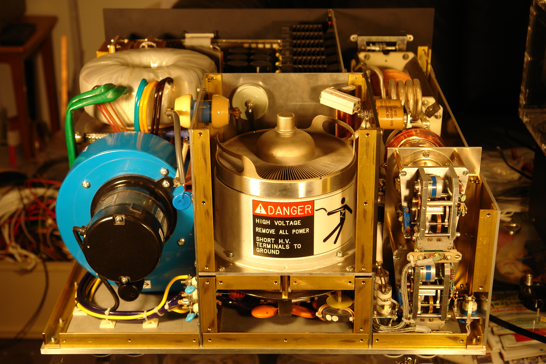
Fig. 10: Power amplifier without back board, the motors for the two vacuum capacitors on the right
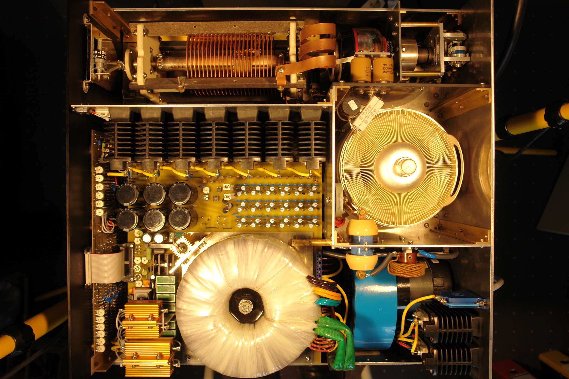
Fig. 11: Finished Tsunami power amplifier; top view, the brand new tube is shining happily!
Click to enlarge image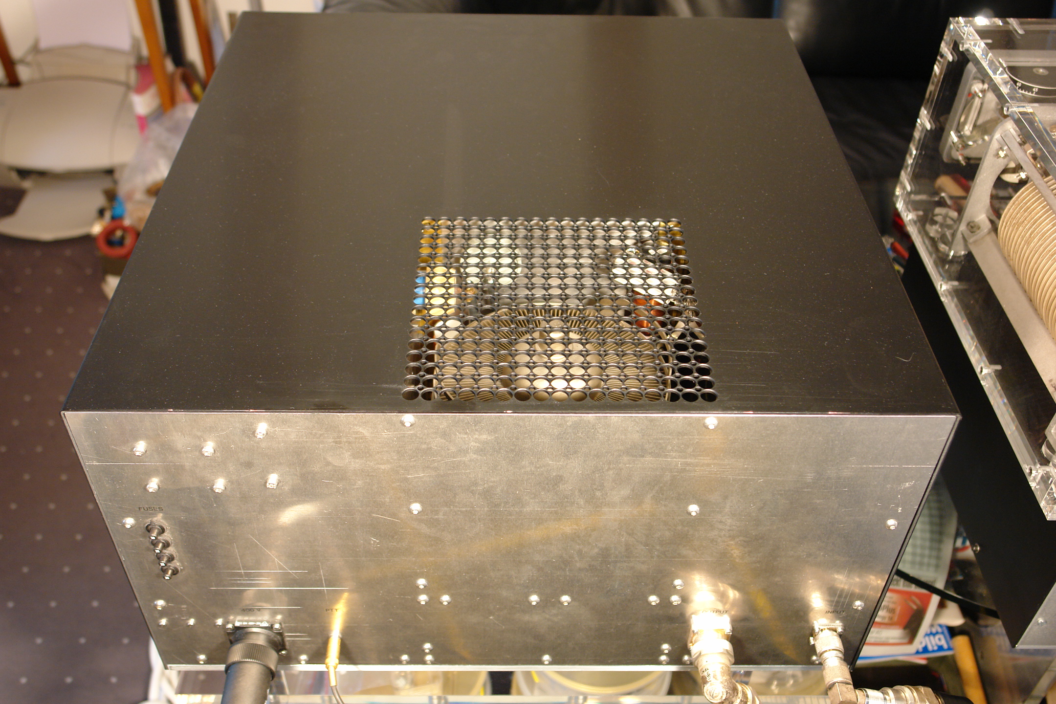
Fig. 12: Tsunami power amplifier; back view (left to right: 4 main fuses (circuit breaker), three-phase alternating current connection (5 x 32 A, 400 V), PTT (cinch), output (7/16), input (SO239))

Fig. 13: Finished Tsunami power amplifier on a sustainable acryl glass table, custom-made
Click to enlarge image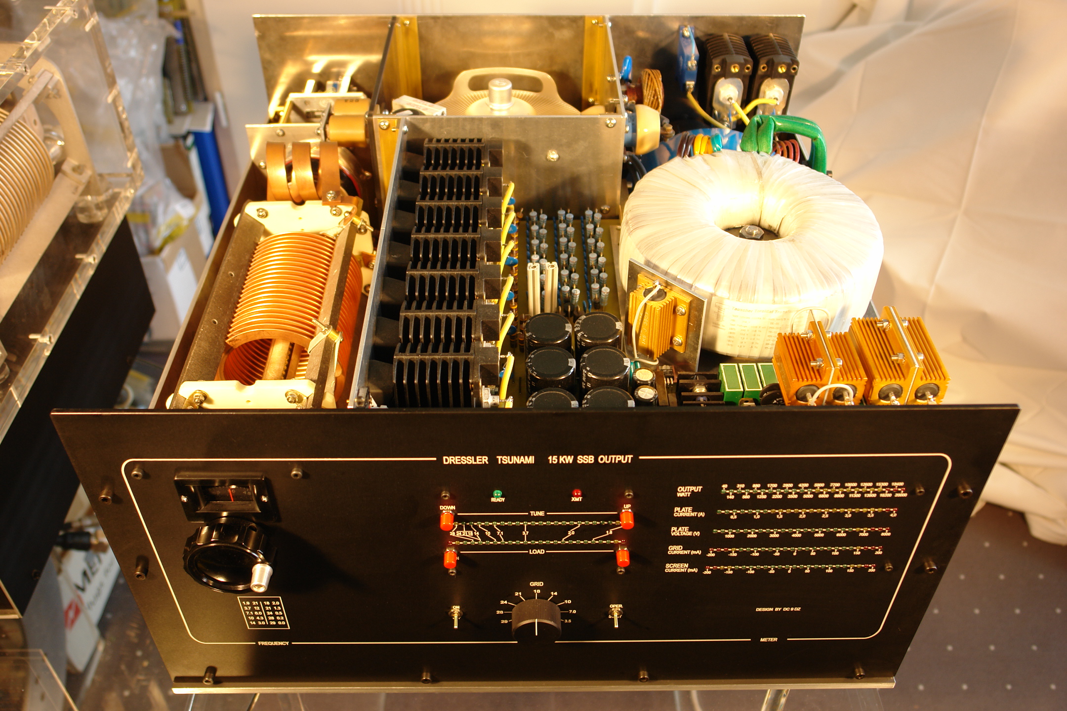
Fig. 14: Finished Tsunami power amplifier: Does anybody know of a smaller 15 KW SSB output stage?
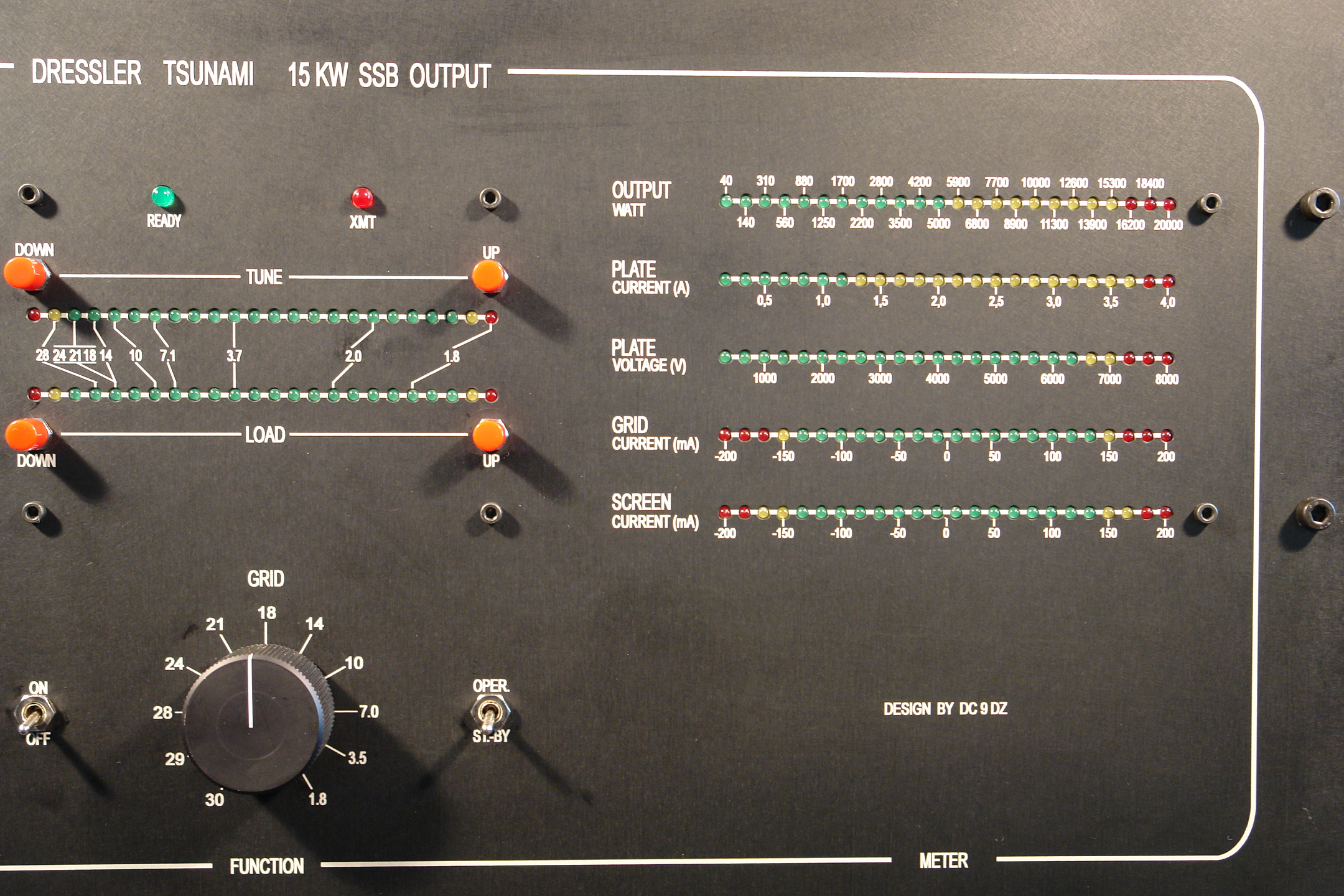
Fig. 15: Detailed view of the laser inscribed front panel
Data of DRESSLER Tsunami RF Linear Amplifier
| Frequency bands | all HF amateur bands | 1.8 MHz to 29.7 MHz | ||
| Power supply | 3 power supply transformers | 10000 VA, 1200 VA & 1 VA | ||
| Plate voltage | 6500 | V | at full output power | |
| Screen voltage | 1000 | V | stabilized | |
| Grid voltage | - 245 | V +/- 20 V | regulated | |
| Filament | 7.5 | V / 75 A | ||
| Input SWR | 160 20 15 12 |
m – 30 m m – 10 m |
< 1.25 : 1 < 1.35 : 1 < 1.45 : 1 < 1.65 : 1 |
|
| Gain | (1.8 – 29.7 MHz) | 20 – 21.6 dB | ||
| Neutralization | (1.8 – 29.7 MHz) | 45 – 50 dB | ||
| Amplification | Input power | Output power | ||
| Equipment: R&S 20 KW Dummy Load, Bird Power Meter Measurements on 7.1 MHz |
5 W 10 W 20 W 30 W 40 W 50 W 60 W 70 W 80 W 90 W 100 W |
0.75 KW 1.5 KW 2.9 KW 4.4 KW 5.8 KW 7.3 KW 8.7 KW 10.1 KW 11.6 KW 13.1 KW 14.6 KW |
||
| Input SSB Signal | 33% of full 1 KHz Modulation on / off Ratio 1:2, Interruptions: 20 Hz |
|||
| Harmonic Output | 50 dB below rated output | |||
| IMD | 35 dB or better | |||
| Tube | Eimac 4CX10000D | |||
| Input network | 1:9 Transformation, 450 Ohm, 500 W HF Resistor, Tube Input Reactance Compensation & Neutralization for each Band, 11 pol. bandswitch, two levels | |||
| Output network | Roller inductor 20 uH & 2 motorized vacuum capacitors 500 pF var. / 15 KV + 2.5 nF var. / 5KV | |||
| Computer control | All switching functions, no relais switching under power conditions, soft start inrush, 10 sec delay time for full power, 2 speed turbine
blower Well regulated screen and grid supply for +ve and -ve currents as well as current limiting to protect the tube and minimize the IMD. It is impossible to override the screen and grid dissipation at any working conditions. |
|||
| Metering | Display of all parameters – no switching | |||
| Housing | High quality black eloxial aluminia | |||
| Dimension | 575w x 310h x 585d mm³ | |||
| Weight | 132 kg | |||
| Accessory (for Icom-Transceivers) | Module for optimized tuning (1 KHz, on / off: 1:2, 20Hz) | |||
| Price | Very low: about 1.7 €/W (1.7 €/W x 14.6 KW = 24.8 K€) | |||
Some comments on the measurements
Measurements of the output power of the Tsunami power amplifier revealed a decreased output at higher frequencies. It turned out that this is mostly due to the ICOM transceiver (IC 7400) as its output is reduced when frequency is increased. Although it still pretended an output power of 100 W on its display, but the actual output at 10 m was only 74 W for example (with tuner).
In general, the RF parts used in the Tsunami output stage are not small in terms of space due to their high performance. Hence, the signal paths and stray capacitances are inevitably larger as, for instance, in a 1 KW power amplifier. Still, the Tsunami features an impressive output power across the full frequency range from 160 m up to 10 m. The complex roller inductor allows for a continuous variation of the operating frequency across a broad frequency range, but the disadvantage is that the requirements of frequency variation, e.g. the skin effect, cannot be accounted for due to the constant turns of the coil. In switched pi filters, the respective inductor parameters like coil diameter, thickness of the conducting layer as well as the distance between the coils can be adjusted according to the desired frequency range, thereby a uniform output is achieved across the full frequency range. However, the Q of the output circuit predetermined by a fixed number of taps, whereas it can be continuously adjusted using a roller inductor. For the Tsunami project, particular attention was devoted to resilience and reliability so the roller inductor that is used was chosen from a set of 8 different inductors according to these aspects. With a modification of its contact finger, the shortest possible contact path between roller inductor and the two vacuum rotary capacitors could be achieved. Also, motorized capacitors were a requirement for the best possible placement of the two pi filter capacitors. It is only due to these artifices that the frequency range of the Tsunami power amplifier completely covers short-wave, including the medium wave region of the 160 m band. The small variation in the amplification factor within the single bands can be easily compensated with a variation in input power.
The performance of the fully assembled Tsunami is well beyond traditional amateur radio means. Of course, one has to especially deal with the performance of antennas, antenna couplers, cable connections and so forth. A 165 m loop antenna, a reasonable open wire feeder and a well dimensioned antenna coupler permit for smooth operation on all bands discussed here, but excessively exceeding legal constraints should not be considered. As the author abides to the rules, the Tsunami is up for sale – but of course the bet has to be won first.
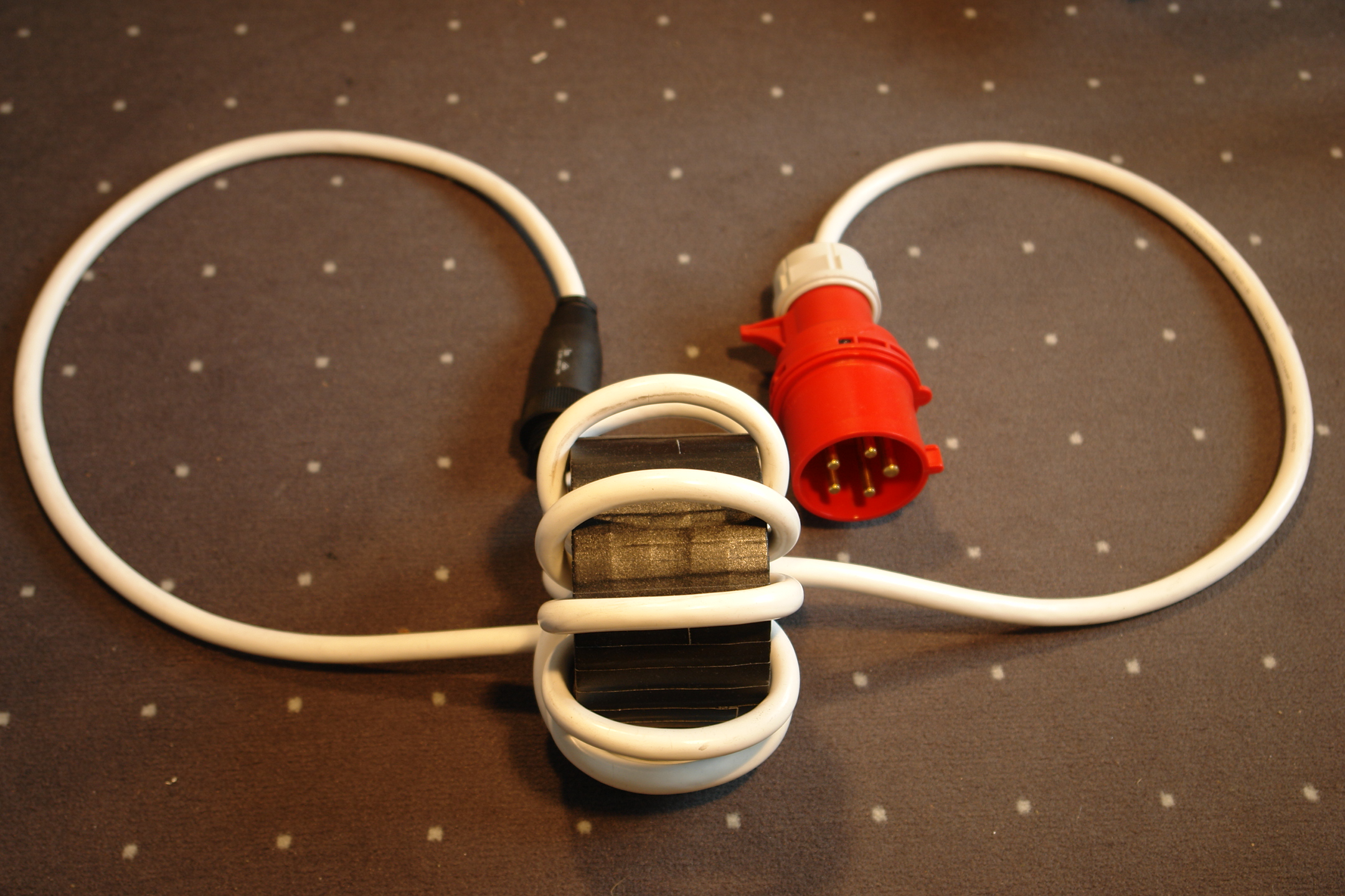
Of course, interfering factors also increase with increasing power. So one has to deal with complications like, e.g. for the author, RF destroying DSL modems. Therefore, a great deal of attention has to be paid to control strayed RF in the system. As soon as ferrite beads were attached to the 230 V and 400 V power cords as well as the PTT and HF control cables, everything was fine again.
So are destroyed DSL modems acceptable for fellow human beings? Of course not! As the German philosopher Max Weber says: Every human is responsible for his own bondage. This can be translated to: One should only create as much power as circumstances and fellow humans permit. ??!
Accessories / Miscellaneous
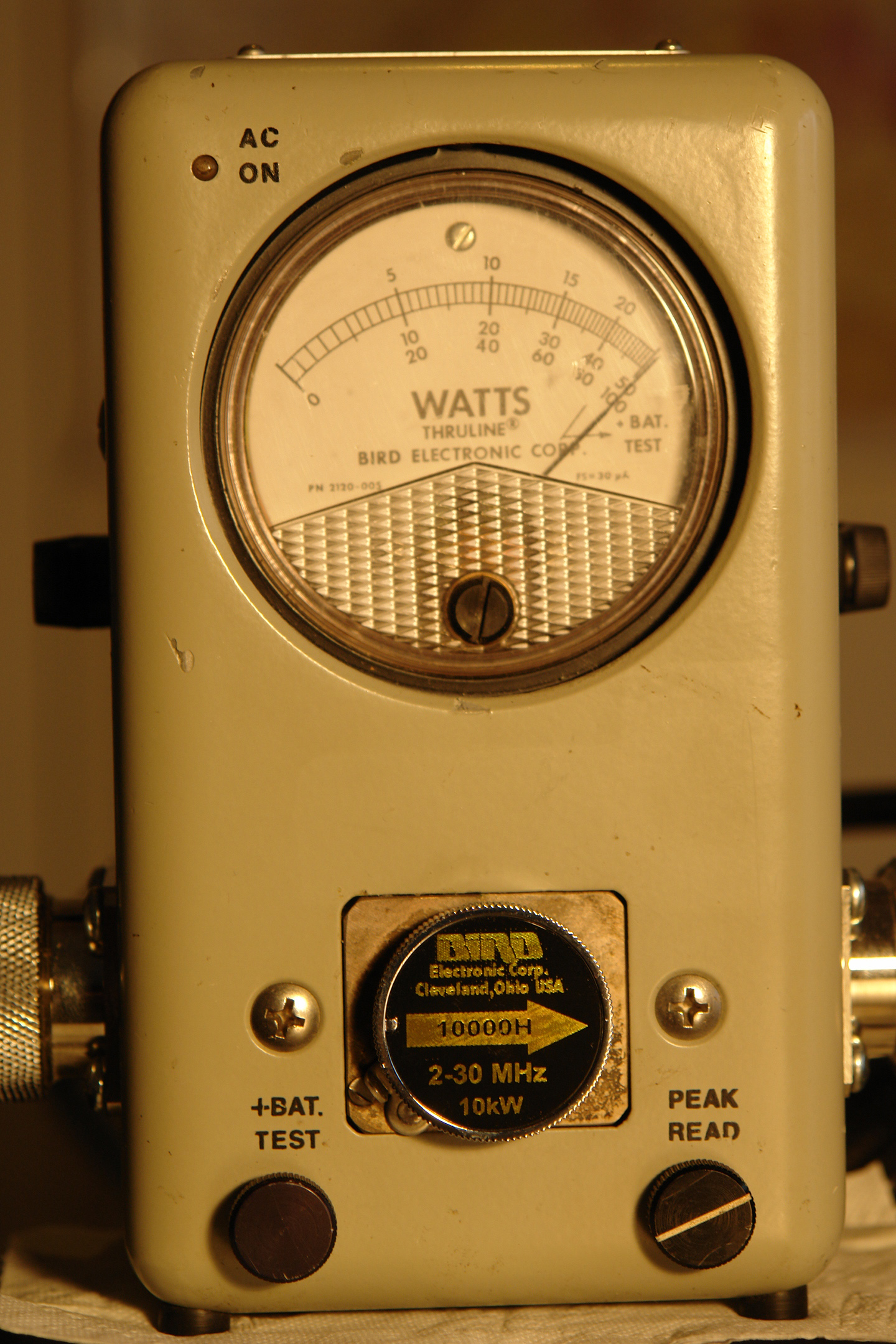
Fig. 16: Proof of output power: With an input of only 70 W on 40 m the Tsunami power amplifier provides an output of 10.1 KW.
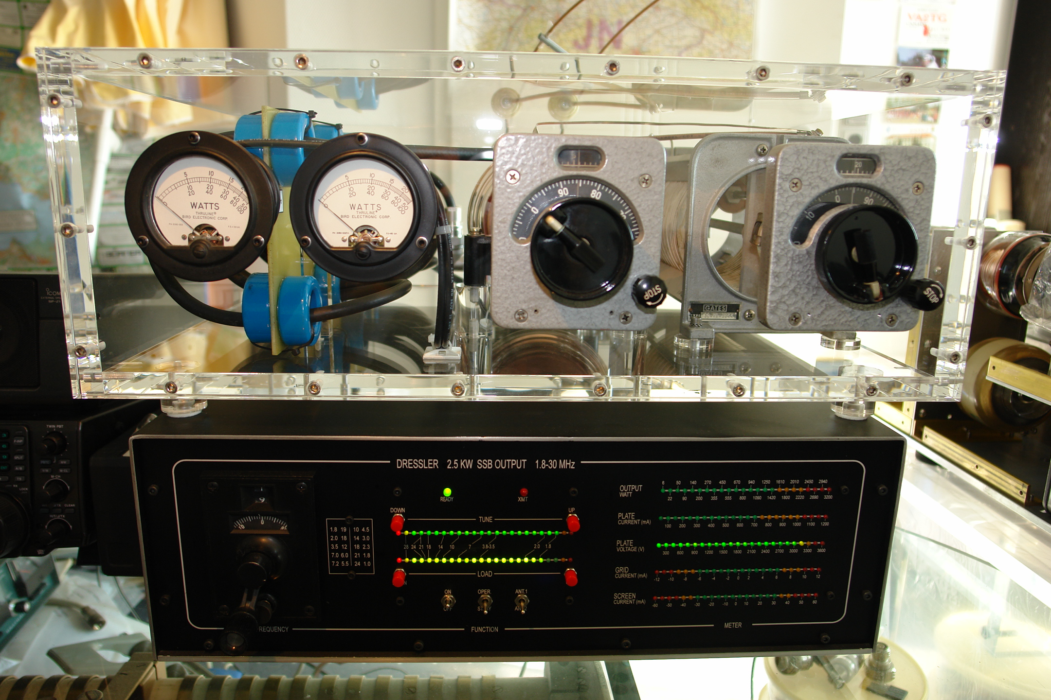
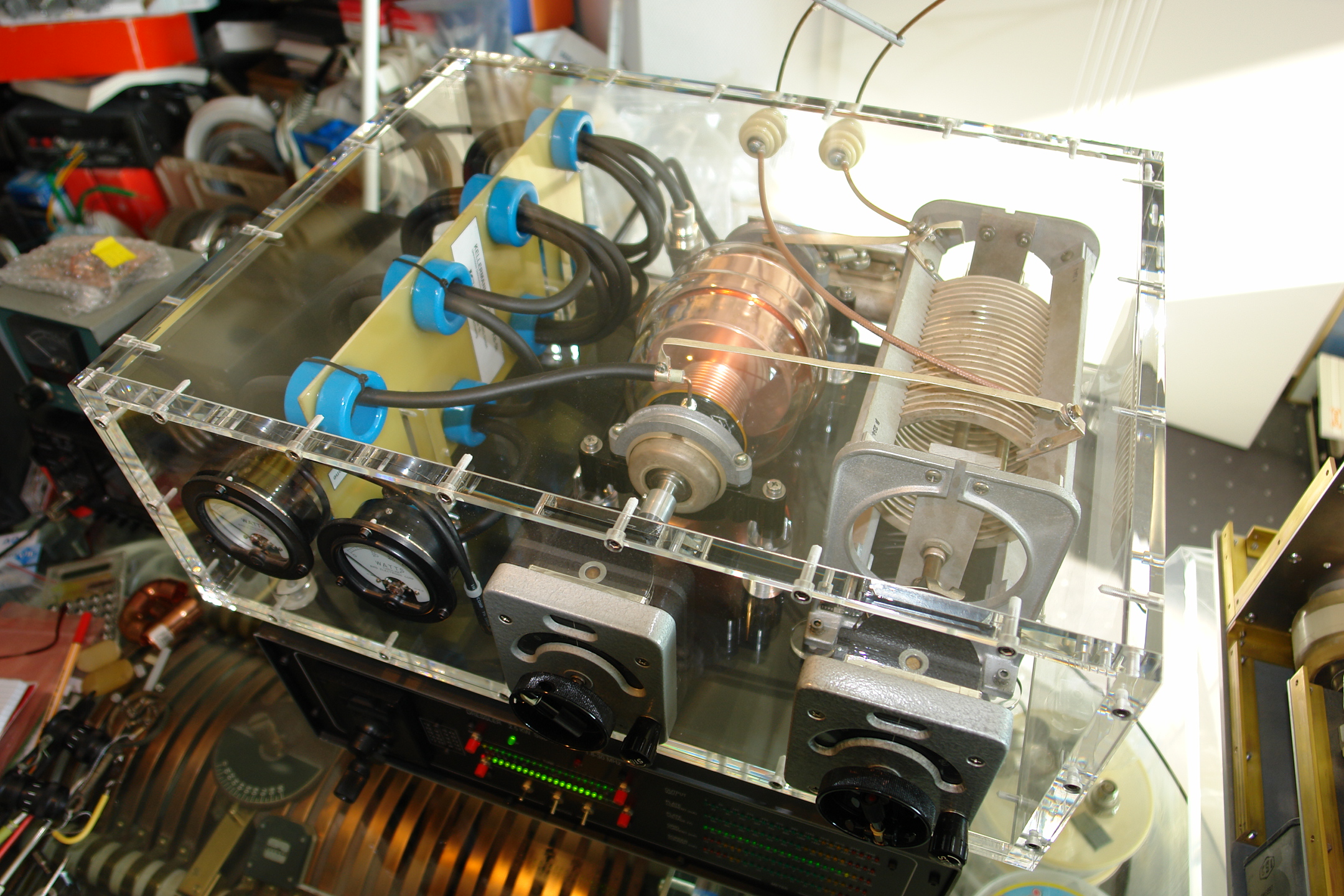
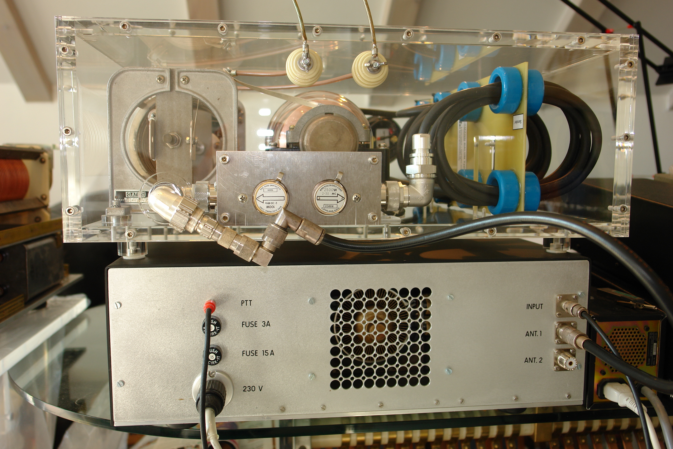
Fig. 17 – 19: The exclusive Tsunami capable antenna coupler in acryl glass, working up to 15 KW SSB output in a frequency range from 160 m up to 10 m. The integrated power meter (original Bird) exactly indicates forward and reflected transmission power, allowing for quick and accurate adjustment of the antenna. The coupler sits ontop an amplifier with a 4CX1500B, which provides an output power of at least 2 KW SSB at a height of 16.5 cm.
Fig. 20: Ferrite bead for 3 x 400 V power cord, weighing about 4 Kg.
The author would like to thank his radio colleagues for the valuable support and assistance during the realization of the Tsunami project.
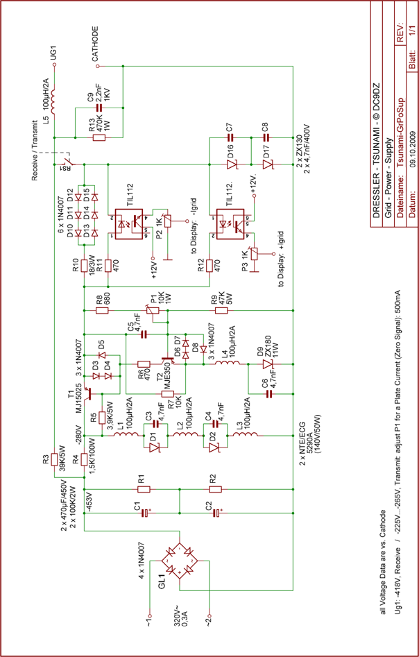
Circuit Diagram RF Deck
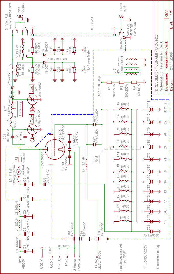
Amplifier Neutralization and Adjustment for best Input SWR
The goal of neutralization is to isolate the anode from the grid at the operating frequency. Neutralization discourages oscillation and guarantees absolute stable operation.
That's all! This completes the neutralizing and adjusting for the best input SWR.
Generally speaking: An input transformer with a 1:4 transformation will give less power amplification (18.5 dB) but band width and input SWR are best and tuning the grid components is very easy and stable. On the contrary with an input step-up transformer of 1:16 the gain will grow to 24 dB but the working band width is very small and the input SWR at the high bands is lousy. With that transformer you must decide at each band for the best amplifier working to choose either the CW or the SSB frequency area. Tuning the grid components in that case is delicate. So the best compromise for gain/bandwidth with the 4CX10000D is a 1:9 input transformer. Due to the input capacitance of the tube, which is also transformed by the step-up transformer (therefore at Tsunami: 350 pF – 400 pF) a broad band transformation for several bands is absolutely impossible.
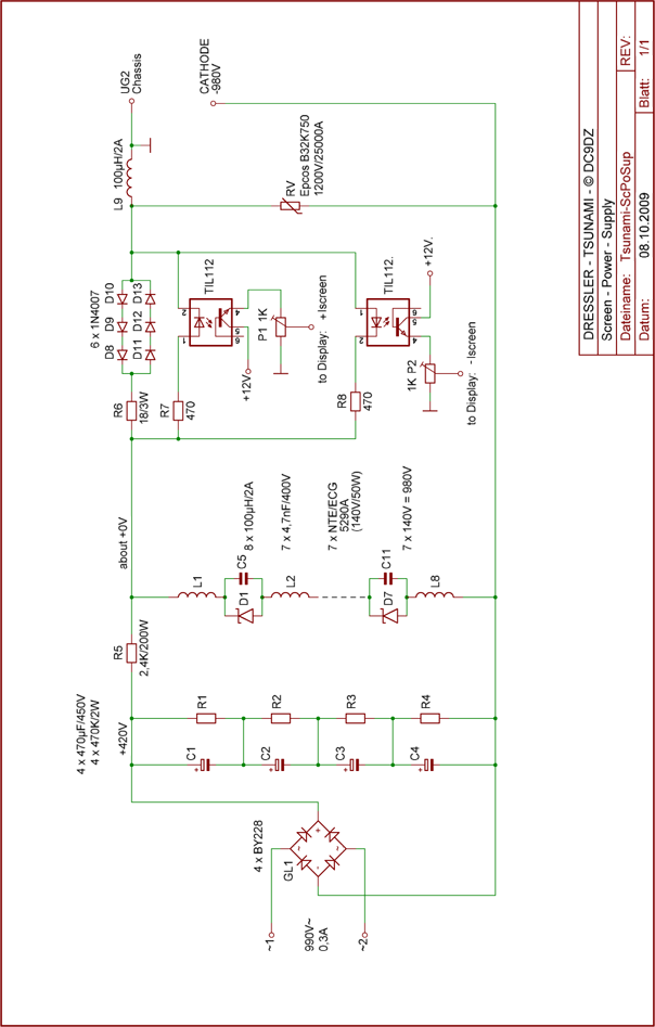
Circuit Diagram Screen Grid
Circuit Diagram Control Grid